Finally the
procedure we have all been waiting for the "A4 Timing Belt
Procedure" including the Automatic and Manual transmission
differences. Some people have argued till they are blue in the
face that "mark and pray" was the easiest way to change one of
these belt, and it has been proven that this belt can be
changed in under 2 hours using the full factory method as
demonstrated here in this thread. The procedure utilizes all
the factory tools and processes. The reason for going to the
extreme of utilizing all the tools is the elimination of all
possibilities of making a $2500.00 mistake and destroying the
head.
You do not need many tools to complete this job. What you
do need is a thorough understanding of the procedure and what
you are about to accomplish. When changing a timing belt you
are doing more than just replacing an old belt. What you are
doing whether performing a 40K on the auto or 60K on a manual
is inspecting the entire engine area that has been covered up
since the engine was new or since the last belt change.
The second most important thing this procedure accomplishes
is it totally resets ALL timing setting on the engine and
restores them back to Factory new settings. While on the topic
of timing we need to understand that there are three types of
timing involved here. The first and most overlooked type of
timing is the cam and crank timing. This keeps the cam
spinning in perfect time allowing the engine to produce great
low end power as well as allowing the engine to rev to it's
full redline of 5100 rpm.
The second type of timing is "Basic" injection timing. I
concocted the word "Basic" timing because it is used to
initially set and assure that the engine will start. This is
accomplished by inserting the injection pump lock pin
positioning the pump shaft in relation to cam and crank timing
in such a way that injection will occur within the ignition
window.
Once the cam & crank timing have been set and the
Injection pump is positioned you will need to adjust the
injection timing utilizing the Vag-Com http://www.ross-tech.com/
If you do not have this then get it before attempting to
perform this procedure.
This leads me to my next point, tools. Everybody wants
to know where to get them and how much they cost. The simple
fact is they are not cheap, but neither is your engine... I
use the factory tools that I got from http://www.zelenda.com/ .
They sell all the tools you need for the job and they are the
same tools the factory used to assemble your beloved engine so
again it's your engine and your money.
The VW Factory tools you are going to need are:
-3036
Camshaft holding bar
-3418 Camshaft setting bar
-2587 2
pin spanner wrench (don't use a bicycle wrench this one costs
the same!)
-3359 Injection pump lock pin
-T40001 puller
set
Specialty tools your going to need from Sears:
-41831f
Serpentine belt tensioner tool
-44360 11mm&10mm 45
degree offset wrench
-5mm 3/8 drive allen socket
-6mm
3/8 drive allen socket
-T25 Torx bit(1/4" drive)
Specialty tools from AutoZone:
Flat Band clamp tool
Other tools and "stuff"
(1) Block of wood, a 2x4 6" long
will work great
(2) Jack stands (strong enough to support
your car!)
(1) Hydraulic floor jack
Tools you have to make:
stubby 5mm 1/4" drive socket

Not to mention a set of metric 1/4, 3/8 and 1/2" drive
sockets and extensions.
Now the fun part! I have to add If I have to explain
how to remove the belly pan and the engine cover you may want
reconsider performing this job and take it too your local
dealer...no joke.
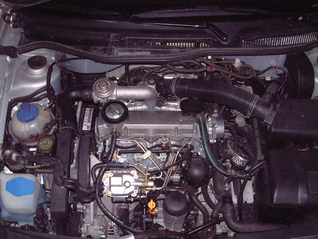
This engine represents a majority of the forum members
in that it has an oil bypass filtration system, bypassed CCV
system (Thank God no oil to drip on me !) and he is a proud
member of Epsilon!
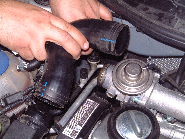
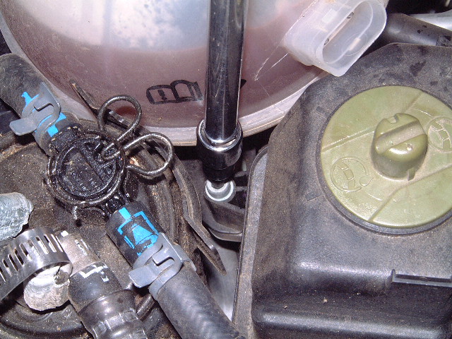
Using the "Flat Band Clamps" remove the intake tube
going into the EGR/intake manifold
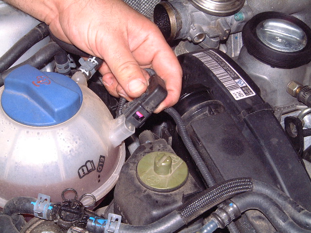
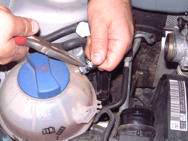
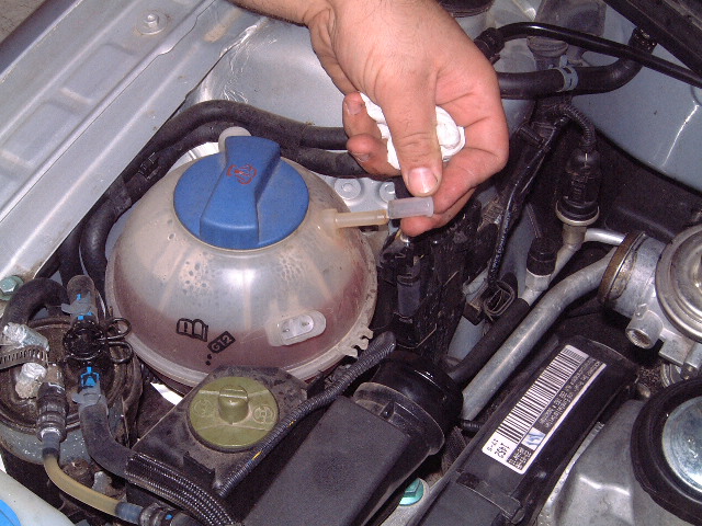
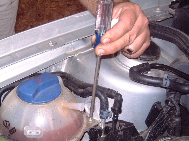
Remove the coolant reservoir connector, hose clamp and
two philps screws.
using a 5mm 3/8 drive allen socket and extension,
remove the allen bolt securing the power steering reservoir to
the engine mount
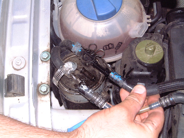
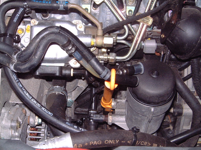
Remove the two fuel lines coming off of the fuel
filter, cap them off and insert them through the oil dip
stick
Stuff some paper towels into the intake to prevent
"Murphy's Law" from kicking in and prevent you from dropping
that flying spring clamp into an intake duct!! 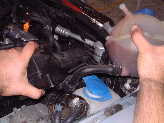
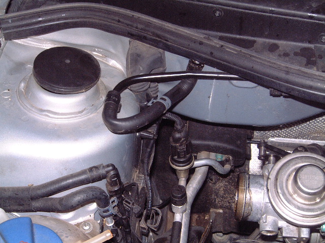
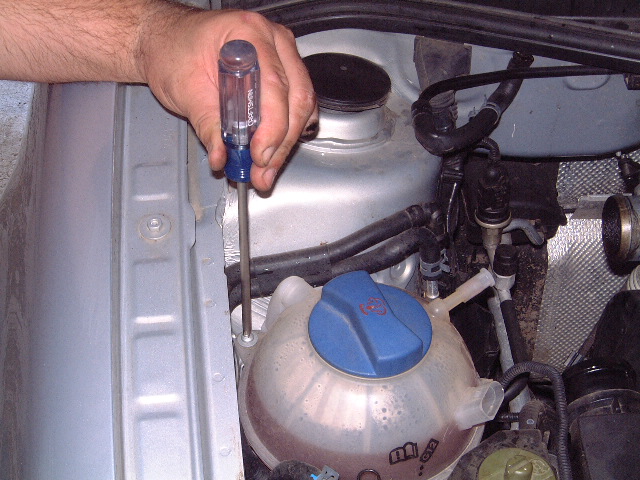
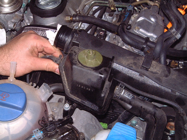
Raise up the power steering reservoir and pull the
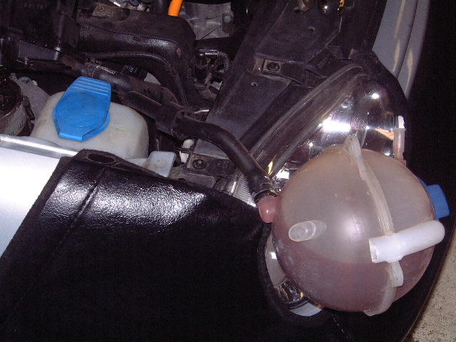
coolant reservoir hose under and to the front of the car. let
the coolant reservoir hang on the front of the car.
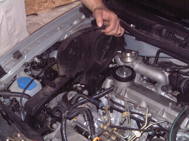
Remove the timing belt cover, and the flex line coming
from the air filter going to the engine, I strongly suggest
stuffing some paper towel in both holes to prevent you from
dropping something into the turbo inlet.
Using a 5mm 3/8 drive allen socket, remove all the
front and driver side rear allen bolts except for the two by
the oil filler cap. For those use the special cut-off 1/4"
drive socket that you made to remove them. Believe me when I
say this, I have tried EVERY possible way to do this and I
have stripped out a few heads in the process and this by far
is the only true easy way to do it.
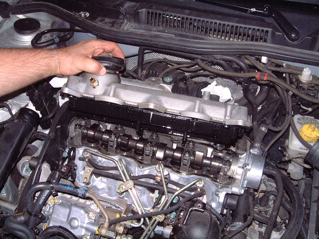
Lets look at the head and gauge what we are going to
do. On the right side of the camshaft is the vacuum pump,
there is a slight difference in removal procedure between the
auto and manual (not a big deal by the way). Anyway on the
left side of the cam look at the first two lobes. These two
lobes MUST ALWAYS be returned to the "both up" position, why
you ask? If you don't its not a matter of if but you WILL wet
the cam timing 180 degrees out of time don't ask how I can
only say from my experience and that of others that it can and
does happen. By the way this is a great example of a SUPER
clean engine using Delvac 1 5w40 full synthetic, the best oil
out there that meets the VW TSB oil viscosity
specifications....had to through that in there
Remove the vacuum line running under the vacuum pump.
MANUAL TRANSMISSION OWNERS, REMOVE THE CENTER GLOW PLUG
WIRE AT THIS POINT AS WELL
Using a 1/4" drive deep socket remove the lower 10mm
nut. MANUAL TRANSMISSION OWNERS, USE THE 45 DEGREE OFFSET
10MM WRENCH AND REMOVE THIS NUT. THE NUT WILL BE BETWEEN THE
COOLANT HEATER HOUSING AND THE VACUME PUMP AND THIS WRENCH IS
THE ONLY WAY TO GET IT OUT WITHOUT REMOVING THE COOLANT HEATER
HOUSING.
Using the 10mm deep, remove the aft 10mm nut, this is
the same for the manual owners as well, then remove the vacuum
line support bracket.
Using a 13mm deep socket, remove the front vacuum pump
bolt There are three of these 1 normal bolt and the other two
have a threaded bolt on the top for the vacuum line support
bracket
Remove the rear vacuum pump bolt
Remove the lower 13mm bolt. MANUAL TRANSMISSION
OWNERS, USE A 13MM BOX WRENCH TO GET IN AND REMOVE THIS BOLT.
THE COOLANT HEATER HOUSING WILL PREVENT YOU FROM USING THE
DEEP SOCKET (BUT I SUPPOSE YOU HAVE NOTICED THAT...)
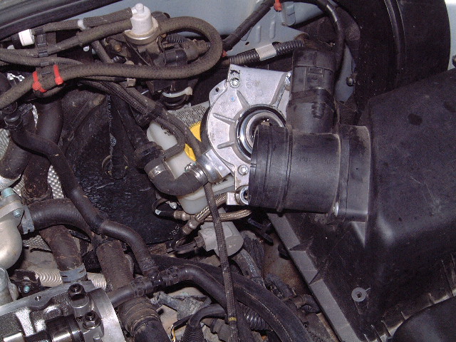
Remove the vacuum pump and bend it out of the way, you
won't damage the line by bending it just make sure it does not
fall damage could result.
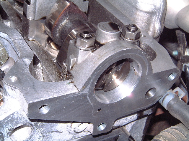
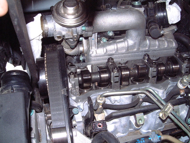
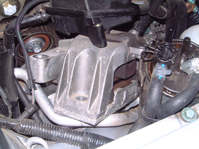
Here is a picture of the end of the camshaft. The
groove in the end of the cam is where the 3418 Cam setting bar
is inserted. In a later step the groove as you would suspect
will need to be rotated, the 3036 Cam Holding bar will be used
to turn the engine into the correct position.
Using your two jack stands and a hydraulic jack, lift
the car and support it at a height that is comfortable for you
to get under the car. Now crawl under and remove the engines
belly pan
Crawl under the car and at the back of the engine above
the passenger side drive shaft is the turbo compressor outlet
pipe. Using your "Flat Band Clamps" remove the spring on
turbos Compressor outlet and pull the hose off of the outlet.
Use a 10mm socket and remove the nut on the turbo to
intercooler pipe, then use the clamps and remove the clamp on
the intercooler and remove the whole duct assembly.
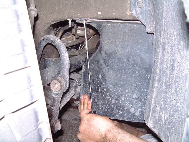
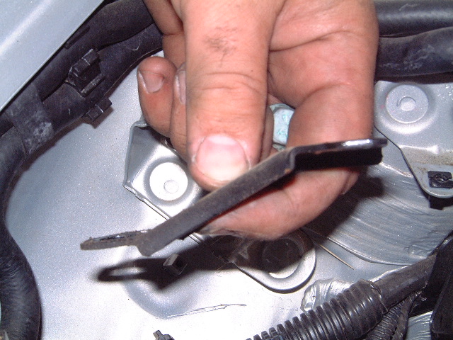
[b]Remove the washer nuts using a long screwdriver by
un-screwing them, or you can just pull off with some force but
you may damage the washer so try this as a last resort. Then
remove the side lower panel.
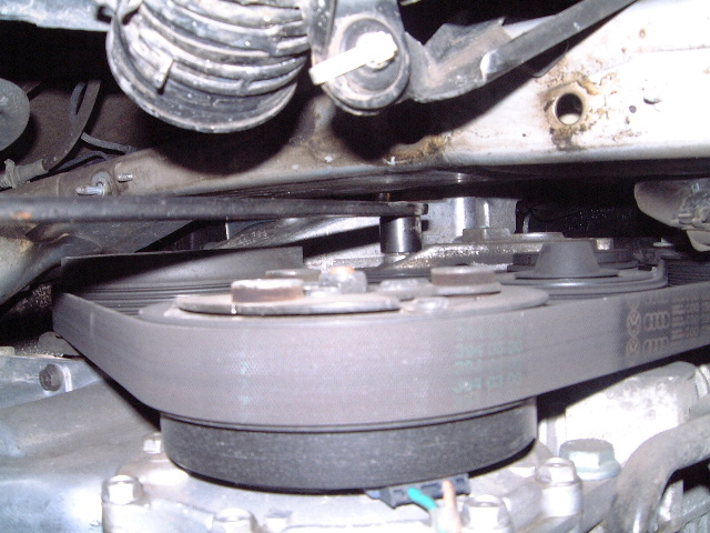
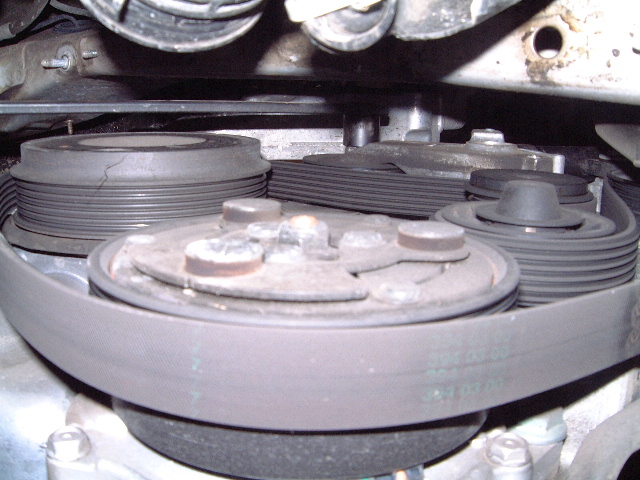
Using the Craftsmen 41831f Serpentine belt tensioner
tool and the special short 16mm socket that came with the
tool. (FYI a standard socket WILL NOT fit in this small space)
Relieve the tension on the serpentine belt tensioner and
remove the belt.
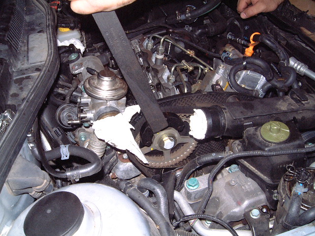
Using the 3036 Cam holding bar, rotate the engine until
the cam lobes on the #1 cylinder (passenger side in "Normal
world") are in the "Lobes up position and the groove in the
cam pulley is level with the machine finished valve cover
deck.
Install the 3418 Cam setting tool into the groove, you
may need to work the cam back and forth a bit with the 3036
tool. The 3418 has a nit of flex to it so it hold the bar nice
and tight in the groove preventing the cam from moving. In the
A3's you needed to use feeler gauges but in the design of this
tool they built in tension that eliminates the need to use
feeler gauges as depicted in the Bentley Manual. THIS IS A
GOT-YA, MAKE SURE THE #1 LOBES ARE IN THE LOBES UP POSITION
BECAUSE OF THE FLEX IN THE 3418 TOOL IT IS POSSIBLE TO FORCE
IT INTO THE GROOVE ON THE CAMSHAFT EVEN THOUGH ITS 180 DEGREES
OUT, TRUST ME ON THIS ONE hehehe

NOTE TO AUTOMATIC OWNERSThis is where the
Bentley fails at depicting what you are looking for. On the
flywheel you are looking for a stamped circle with a "minus"
sign on either side. The first link shows the timing mark when
the cam setting bar was first installed. It should look like
the second link with the circle and dashes at the very bottom
of the window. At this point do not worry about the crank
timing it is however "VERY" important for you to know what it
looks like because of all the marks that can be construed as a
"TDC" mark.

NOTE FOR MANUAL TRANSMISSION OWNERS this is a
picture of the timing mark and the hole to observe it through.
The hole is located at the very top of the transmission
bellhousing (12 O'clock postion).
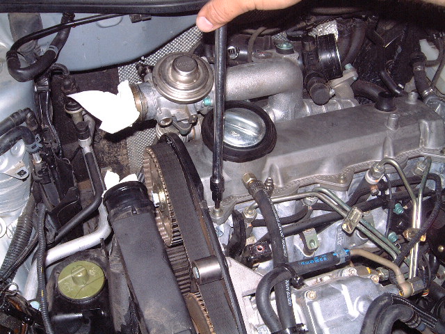
Moving back over to the Pendulum Engine mount by the
Power steering reservoir, use a 13mm with an extension to
remove the steel engine mount alignment plate.
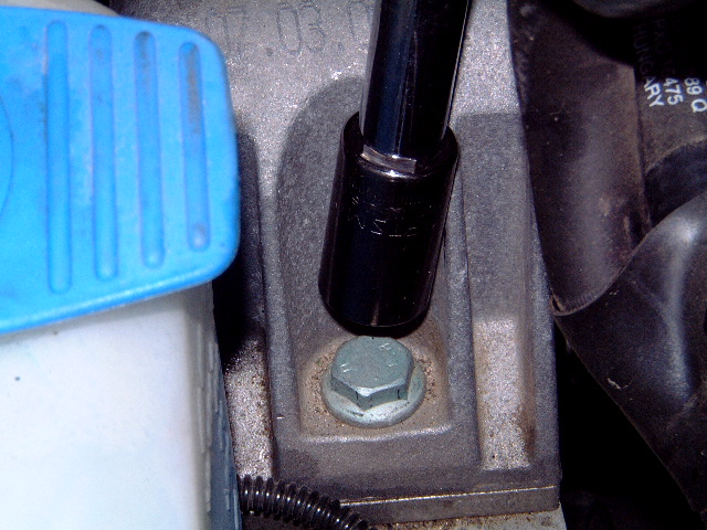
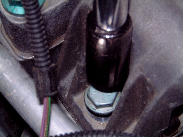
Remove the two lower bolts using a 1/2" drive and 16mm
socket If you have to use an 18mm these are the WRONG
BOLTS!
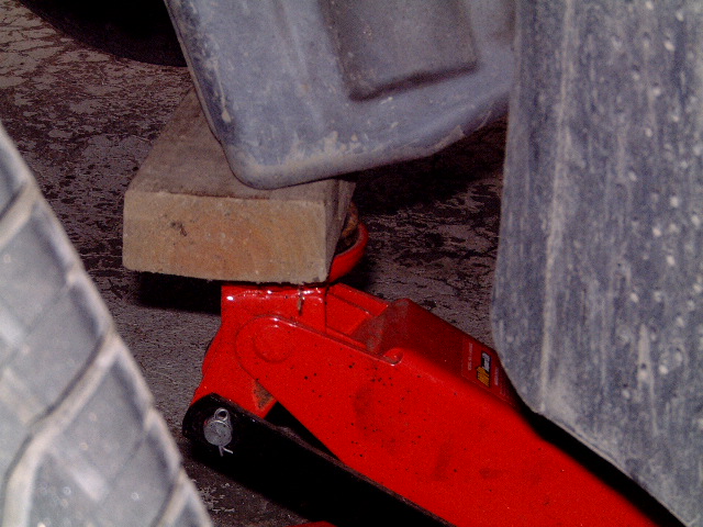
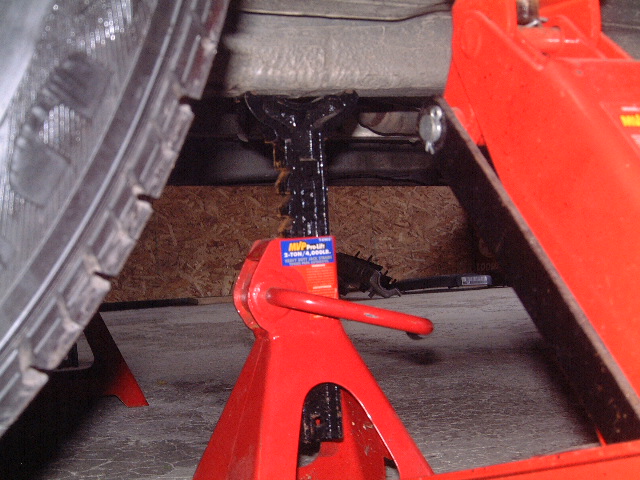
Grab your hydraulic floor jack and the 6" 2x4 piece of
wood, position the wood and the jack on the rear passenger
side corner of the oil pan. NOTE: MAKE SURE THE WOOD IS ON
THE EDGE THE REASON IS STRUCTURALLY THIS IS THE ABSOLUTE
STRONGEST PART OF THE PAN AND WILL PREVENT YOU FROM CRUSHING
IT IF ANYTHING WERE TO SHIFT OR DROP. Once the jack is
positioned under the pan lift the engine until the engine
weight is off of the mount and so that the engine mount is off
the car frame by about an inch.
With the engines weight off of the engine mount use a
1/2" 18mm socket and breaker bar (this is a tight bugger) and
remove both of the remaining engine mount bolts.

Slide the engine mount out of its position and remove
from he car.


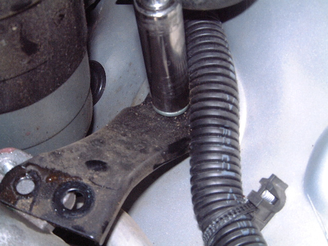
Now carefully raise the engine on the jack until the
engine mount bracket hole is exposed so you can get a socket
in. Don't worry you will not damage the other mounts in doing
this. You may have to raise the engine quite a bit so don't be
surprised (your knuckles will thank you the higher you raise
it...) Now use a 3/8 drive ratchet and a deep 16mm socket and
remove the front and center engine mount bolt and the super
secret hidden rear one, this one you will have to find by
feel, but I can assure it is there!


Lower the engine on the jack so that you can have
access to all four of the allen bolts on the Harmonic Damper.
Then use a 3/8 drive ratchet or breaker bar and a 3/8 drive
6mm allen socket break loose and remove the allen bolts.
NOTE: DO NOT USE AN EXTENSION OR ELSE YOU RISK STRIPPING
THE BOLT HEADS. FYI the cam setting bar will kee the
engine from moving. On the manual you could put the engine in
gear and keep it from moving by having somebody hold the brake
pedal down, so this method works for both but at least the
manual tranny folks know there is an option.

Use a 3/8 drive ratchet and 16mm socket to break loose
the engine mount but don't remove the bolt yet.


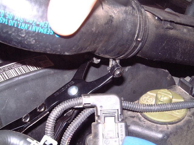
Get a 1/4 drive and a 10mm deep socket and remove the
(5) bolts that hold the timing belt cover plates on. Remove
the last 16mm bolt holding on the engine mount and push the
mount upward to remove the top timing belt cover plate
NOTE: THE TOP COVER CAN ONLY BE REMOVED ONCE THE LOWER
ENGINE MOUNT BOLT IS REMOVED. WHEN RE ASSEMBLING THE ENGINE
THE LOWER COVER MUST BE INSTALLED FIRST FOLLOWED BY THE TOP
COVER THEN THE ENGINE MOUNT CAN BE INSTALLED IN THAT
ORDER. Also notice the rotational direction of the timing
belt. Look for oil leaks or anything that is out of order, now
is when you want to find it.


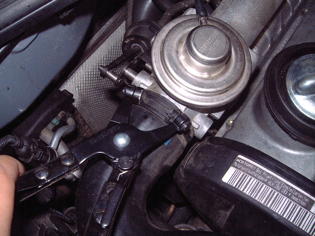
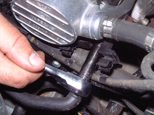
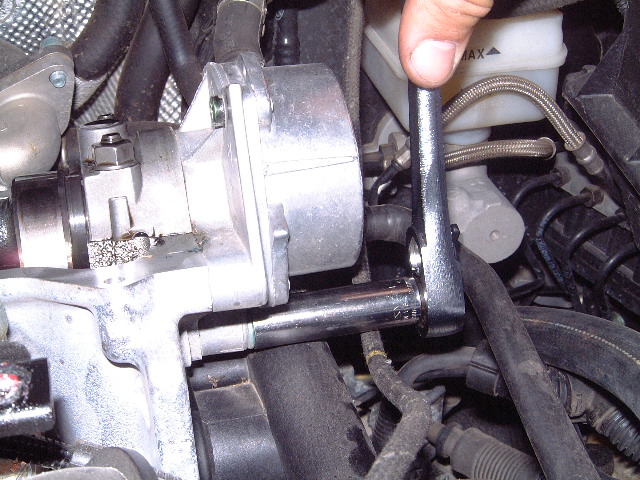
Remove the 13mm nut on the tensioner, and using the
2587 Two pin spanner wrench and relieve the tension on the
timing belt tensioner by rotating the wrench
counter-clockwise.


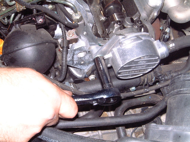
Using the 3036 cam holding bar and a 19mm 1/2" drive
socket loosen but DO NOT REMOVE THE BOLT ON THE CAMSHAFT. The
bolt at the factory was tightened to only 33 ft-lbs. so it
should not require much force at all to loosen this bolt.
NOTE: I HAVE RUN ACCROSS A FEW BOLTS THAT WERE WAY OVER
TIGHTENTED, USE EXTREME CARE IN REMOVING THESE TYPE OF
BOLTS!!!! IF THIS IS THE CASE I STRONGLY SUGGEST REMOVING THE
CAM SETTING BAR UNTIL THE BOLT HAS BEEN LOOSENED AND THEN
REINSTALLING IT.


Install the T40001 puller using the 2 prong puller and
one of the single prong pullers (it comes with 2 single prongs
and one 2 prong grippers). Install the puller making sure that
there is a gap between the washer and the pulley. Use a 17mm
box end wrench and turn the puller until the pulley "SNAPS"
(it will scare you if you don't expect it) off the tapered end
of the camshaft.


Remove the cam pulley bolt, the pulley and the
tensioner pulley from its shaft

Holding the engine mount away from the engine slide the
old belt between the mount and the block, if you have not
noticed yet the mount cannot be removed unless the engine is
removed from the car... Remove the belt and inspect it for any
cracking or rubbing damage. This is when you want to make sure
the belt was wearing normally with only minor cracking or wear
marks visible. If any abnormal wear marks are present you need
to determine how and where they came from so that you do not
install a good belt in a poorly aligned engine pulley
system.


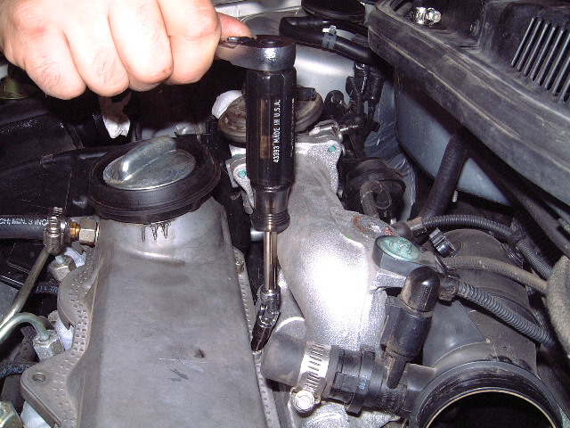
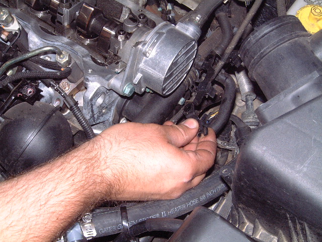
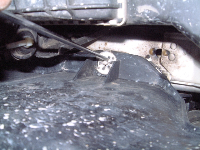
The first picture is a shot of the hole the 3359
Injection pump lock in gets installed into. The second
pictures shows me using a crescent wrench to turn the center
bolt to align the pin hole so that I can insert the lock pin.
The last picture shows the orientation of the pin relative to
the center of the pump. NOTE: IT IS POSSIBLE TO INSTALL THE
PIN TO THE RIGHT OF THE HOLE AND HAVE THE INJECTION TIMING OFF
BY ABOUT 30 DEGREES, WHICH HAPPENS TO BE OUTSIDE THE IGNITION
WINDOW, A NO START WILL RESULT. FYI DO NOT try and turn
the whole motor over using the injection pump center bolt! Use
the 3036 tool. Rotating only the pump such as I have
demonstrated will not loosen or throw the pump shaft alignment
off since I am only turning the pumps pulley with out a timing
belt installed.


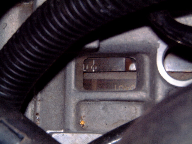
NOTE THIS IS THE AUTOMATIC TRANSMISSION TDC TIMING
MARK. If you look at the first picture notice that the
circle is at the base of the window, this is what you want. If
you have to turn the crank use a screwdriver and gently push
the fly wheel in the direction you need to go to get the TDC
in the correct position of the window. Then insert the small
screw driver to prevent the flywheel from spinning when
installing the new belt.
NOTE: THIS IS THE TIMING MARK ON THE MANUAL
TRANSMISSIONS. Make sure the mark lines up with the
aluminum tooth at the top of the hole.

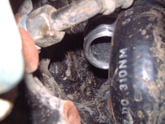
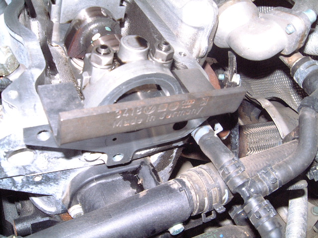
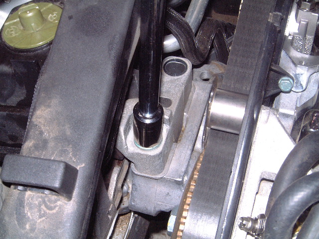
This is a picture of the water pump. If you have
120,000 miles or more consider replacing it. It's only a few
bolts and a gallon or so of coolant. This is a great time to
do the job if you have high mileage.

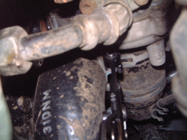
Here is a picture of the timing belt and its part
number for the A4 TDI. I strongly suggest making it very clear
to the part supplier what type of car you have. It has
happened more than once a part counter guy has looked up and
sold the wrong part leaving you with a car that is out of
commission and the possibility of facing a backorder!. Take
your time when researching the parts and double check you have
the correct parts before beginning this job, at this stage in
the game is the last time to realize the belt or tensioner DO
NOT fit!

Hold the belt up and install it so that the curves go
this way, it makes it easier to install the belt around the
pulleys.
[b]Holding the engine mount away from the engine slide the
new belt back under and onto the engine. Route the belt around
the appropriate pulleys, in case you forgot how they go on the
lower pulleys here is a snap shot for you:

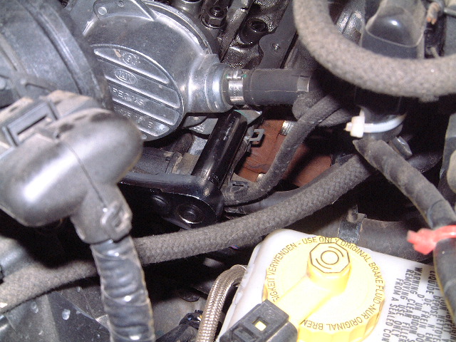
[b]Install the new tensioner. In this picture you see the
two holes on the inner hub at the top of the shaft, you DO NOT
want it here. rotate the two holes so that they are at the
bottom. Also make sure that the alignment prong is engaged in
the slot in the head. Go ahead and install the nut finger
tight only.


Starting from the crankshaft and working counter
clockwise of the belts path around the pulleys take out the
slack and make sure the belt is engaged in all the pulley
teeth on all the pulleys. Once you work your way back up to
the camshaft install the cam pulley into the belt and slide
the pulley onto the cam. This may take a couple of tries but
it will go on, the belt is going to be very snug. What you are
working against is injection pump pulley. Once you get the cam
pulley on install the cam bolt but DO NOT TIGHTEN, make sure
it is only finger tight!.
Once the cam pulley is on, loosen but do not remove the
three blue bolts on the injection pump. This will relieve the
stress on the belt betwwen the injection pump and the camp
pulley as well as the lock pin. I suggest getting the new
style non-stretch bolts, the older style stretch type were
depicted by an "x" in the part number Avoid these if possible.
The new style non-stretch are suitable for use on ALL A4
TDI's.
You can visually determine the non stretch style bolt by
looking to see if the bolts have threads all the way up the
shaft to the integrated washer head, the stretch type threads
stop half-way up the shaft. Anyway when you loosen the
injection pump bolts remove one to inspect it for the type of
bolt installed.
With the 3 pump bolts loosened and the injection pump lock
pin installed this will assure you that the injection pump is
set within the ignition window. I call the setting "basic"
pump timing as it pertains to a mechanical setting rather than
anything to do with the ECU or "Basic Settings" as recognized
by the VAG-COM. Keep in mind having the pump set with the pin
will only assure you the engine will start and run, however it
will not give you an optimum setting for efficiency or power.
At the end of the procedure I will explain how to adjust the
timing using the VAG-COM to get the best power and economy
from your TDI.


Snug up the 13mm nut just enough and insert the 2587
Two Pin spanner and rotate the tensioner "CLOCKWISE" until the
marks (a tooth and a groove) are lined up as depicted in the
last picture. You will notice that when you set the tension
the cam pulley and the injection pump pulley will move as you
take up the slack, this is the whole idea of doing it this
way. The magic is even though the pulleys move the pump, cam
and crank all remain in perfect time! Now lock down the bolt
"Good'n Tight" is a good torque setting.

Double check that the engine mark is still at TDC, the
injection pump lock pin is inserted all the way into the pump,
and that the Cam locking bar is fully seated. Now using the
3036 Cam holding bar torque the bolt to 33ft-lbs. I usually
add just a hair but under no circumstance should this bolt be
over torqued. If it is it can snap the end of the camshaft
off, now you have problems.
Torque down the three injection pump bolts where they are
at.
Double check that the flywheel is still at TDC.
At this point you have the cam locked down, a small
screwdriver wedged in the bell housing holding the flywheel at
TDC, the injection pump lock pin installed in the pump and all
the bolts on the pulleys tightened. The pulley bolts you want
taight at this point are the 3 bolts in the pump, the cam bolt
(33 ft-lbs) and the tensioner nut.

Remove the cam lock bar, injection pump lock pin, screw
driver in the bell housing. REMOVE ALL THE PAPER TOWELS IN
THE INLETS, INCLUDING THEAIR BOX, TURBO INLET, EGR INLET, AND
ANYTHING ELSE THAT WAS PLUGGED.
NOTE: INSTALL THE LONG ENGINE MOUNT BOLT IN THE CENTER
ENGINE MOUNT HOLE TO PREVENT THE NEW TIMING BELT FROM RUBBING
ON THE ENGINE MOUNT IN THE NEXT FEW STEPS.
Using the 3036 holding bar rotate the camshaft counter
clockwise ONLY!! or else you screw up the tension that is set
on the tensioner!! Turn the camshaft/engine one complete
rotation until the the #1 cylinder is back to the "Lobes up"
position (FYI you should feel really good compression when
doing this however compression goes away valves incorrectly
timed do not! If you feel like the engine is hitting a valve
turn it back and recheck all your settings and bolts to make
sure you torqued everything. In the unlikely event that you
got the timing incorrect you cannot damage anything provided
you rotate the engine by hand. If at anytime you change a
timing setting at the cam recheck the rotational clearance
using the 3036 tool and turning the cam one rotation).

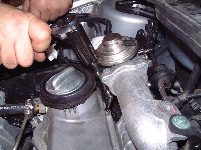
Install the front and rear bolt in the vacume pump so
that the oil feed does not shoot oil all over the engine bay.
Be carefull to make sure the o-ring is not pinched in when
tightening it down.
Once you complete a camshaft revolution check that you can
see the TDC mark in your bellhousing window, if you do your
ready to bump the motor.
With somebody in the car you are going to bump the engine
using the starter. The reason is this will get the new timing
belt properly centered on the pulleys and allow the tensioner
to take up any slack in the timing belt. Try not to let the
engine start and bump the engine as many times as required
(3-4 times) until the belt stops moving and is centered on the
"CAMSHAFT" pulley. The injection pump will be somewhat off
center that's totally normal you just want to make sure that
the belt is not riding off the injection pump pulley, if it is
you need to have the bracket either replaced or reshimmed.
Now that you have bumped the motor clear every intake port
once more and start the motor, it should start immediately and
run normally, if not recheck all timing marks you missed
something. When the engine starts shut it off to prevent oil
from going everywhere.
When your closing every thing up a few things to remember:
-Timing belt covers, install the lower cover first, then
the top cover then the engine mount.
-When installing the pendulum mount install the steel
alignment bracket first then install the big mounting bolts.
-Use blue locktite on the 4 harmonic damper bolts.
VAG-COM timing procedure
Start the engine and let it run. Hook up the Vag-Com and
start the software and enter data block 000. Enter "Basic
Settings mode". Read data block 2 and data block 9. If block 9
(fuel temp) is reading 110 then block two should be reading
70. I doubt it is since the timing is only set to be in the
ignition window so shut the engine down. Loosen the three
bolts (DO NOT REMOVE THEM!) on the injection pump. Using your
trusty large crescent wrench gently and very very slowely
rotate the pump counterclockwise to make the number in block 2
increase or clockwise to make it decrease. Increasing the
value of the number in block two will effectively "Advance
your timing".
You of course will have to guess at how much you moved the
pump, retighten the 3 bolts get in start the engine and see
where its at. If the number is not where you want it repeat
the procedure until the setting is where you want on the graph
in the bentley manual (sometimes I am glad one of my cars is
an A3....)
FYI, advancing the timing will reduce smoke output,
increase fuel economy, and make the engine more rev happy. It
will not matter if you are running the .184, .205 or .216
injectors becuase the #3 injector tells the ECU when injection
occurs so the ECU will have all that taken care of.
Break time....my hands hurt
Drivbiwire